Draw a Mohrs Circle Diagram for Uniaxial Compression
Intro and Derivation
Mohr's circle is a geometric representation of airplane (2d) stress transformation and allows u.s. to quickly visualize how the normal (σ) and shear (τ) stress components modify as their plane changes orientation.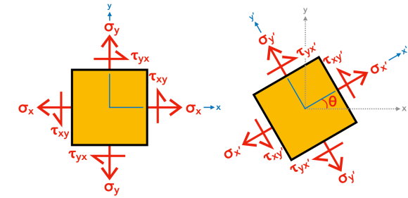 German civil engineer Otto Mohr adult this method from the good ol' stress transformation equations. Call back:
 If we remove θ past squaring both sides of each equation and so add the ii equations together, nosotros get:
![]() Subsequently defining σavg and R, we tin modify Equation three to become Equation four, which is the equation for a circle with eye (σavg,0) and radius R.
Subsequently defining σavg and R, we tin modify Equation three to become Equation four, which is the equation for a circle with eye (σavg,0) and radius R.

Sign Convention
The sign convention for normal stress (σ) is that tension is positive and compression is negative . Shear stress (τ) is illustrated beneath. Geotechnical engineers may employ the opposite sign conventions, because they mostly deal with compressive stress.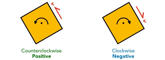 Mohr'southward circle is drawn with normal stress (σ) plotted on the abscissa (horizontal axis) and shear stress (τ) plotted on the ordinate (vertical centrality). Normal stress (σ) is positive to the correct, and shear stress (τ) is positive downward.
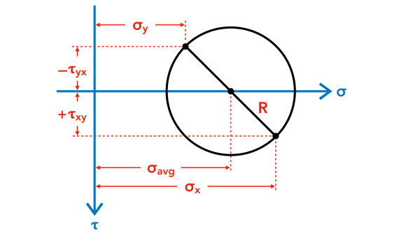
Pole Method
Most mechanics of materials textbooks prefer using the Double Angle Method to depict Mohr's circles. The general idea of this arroyo is that angles between radial lines in the Mohr'south circle are twice the actual angles between the real planes. In other words, a xl° rotation on the plane corresponds to an fourscore° rotation on the circumvolve in the same direction.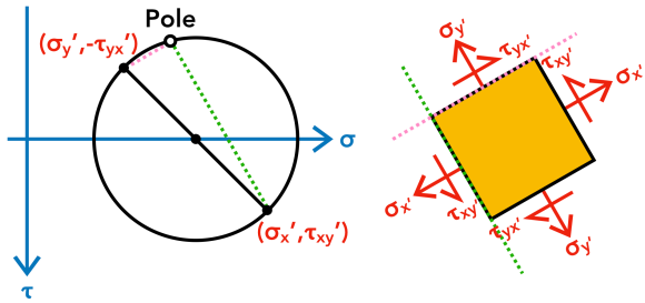 We prefer thePole Method, which is based on a unique point on the Mohr'south circle known as thepole. This pole is unique, because any direct line drawn through the pole intersects the Mohr's circle at a signal representing the state of stress on a plane with the aforementioned orientation every bit the line. Every bit shown in the figure above, a line drawn through the pole and some stress point (σ,𝜏) on the circle isexactly parallel to the plane with respective σ and 𝜏, making this approach very intuitive! Let us illustrate how the pole method works.
To describe a Mohr's circumvolve, nosotros need to know the plane land of stresses for an chemical element. Consider this: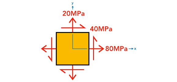 1. Plot the Stresses
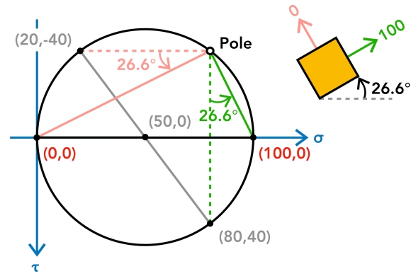
Immediately, we know the ii points that grade the diameter of the circle, (σx,𝜏xy) = (eighty,40) and (σy,𝜏yx) = (twenty,-40). (If y'all are asking why 𝜏yx is -40, recollect the sign convention for shear stress!) The heart of the circle is the halfway point between σx and σy, or σavg.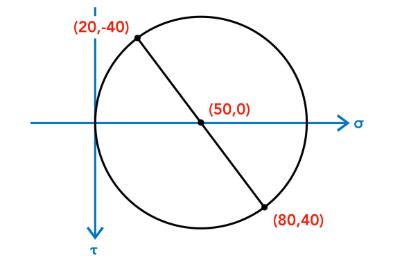 2. Locate the Pole
Draw a straight line from one of the known stress points on the circle (σ,τ) in the direction of the plane on which (σ,τ) acts. Starting at point (lxxx,40), a line is drawn parallel to the plane on which (80,40) acts. This is represented by the vertical dotted green line in the figure below. Starting at indicate (xx,-forty), a second line is drawn parallel to the plane on which (20,-40) acts. This is represented by the horizontal dotted pink line in the same figure below. The pole is at the intersection of these dotted lines on the circumvolve. Note that in that location is simply 1 pole!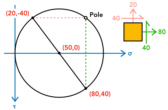
three. Notice Transformed Stresses (e.g. 30° CCW Rotation)
To find other states of stresses, we first drawing the lines from the pole instead of a known stress indicate (σ,τ). This is the general process:
- Draw a line from the pole in the direction of orientation of the transformed plane.
- The indicate where this line intersects the circle represents the state of stress acting on that plane.
Allow us assume a 30° counterclockwise (CCW) rotation of the element. Starting at the pole, to find the transformed counterpart of (twenty,-40), we draw a new line that is 30° CCW from the existing dotted pink line. The transformed stresses on this aeroplane is where the new pinkish line intersects the circle. Similarly, to find the transformed counterpart of (eighty,twoscore), we draw a new line from the pole that is 30° CCW from the existing dotted green line. The transformed stresses on this plane is where the new greenish line intersects the circle. Staying consistent with the rules, the new lines are parallel to their respective planes. The transformed stresses are:
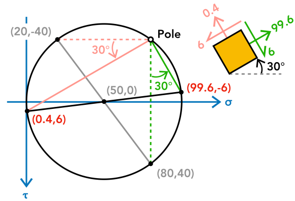
To get these transformed stress values past hand, we would need a protractor to measure the angle and a ruler to connect the pole to the bespeak of intersection on the circle. This tin seem like an elaborate process, and it goes to show that hand-calculating plane stress transformations via Mohr'due south circumvolve is simply an gauge method. To become the verbal transformed stress values, nosotros can use the good ol' stress transformation equations.
4. Check with Analytical Method
Using the the stress transformation equations (Equations one and two):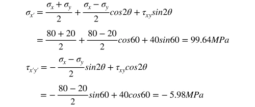 Considering the center of the circumvolve, or σavg, is the same (the circle does NOT movement!), we tin detect σy'.
![]() 5. Principal Stresses
5. Principal Stresses
Primary stresses human activity on planes where τ = 0. The larger principal stress is called themajor main stress, and the smaller main stress is called themodest principal stress.
Similar to finding transformed stresses, we depict lines from the pole to where τ = 0, or the two "x-intercepts" on the circle. The major and modest principal stresses are 100MPa and 0MPa, respectively. The angle, or the rotation required to reach zero shear stress on the plane, is measured betwixt either pair of the original (dotted) line and the new line connecting the pole to the "10-intercept".
Square vs. Triangle
Some textbooks prove stress elements as squares (similar in this article), while others prove them as triangles. They are ii different representations of the same element, because the triangles are merely corner cutouts from the square, every bit shown below by the two a-a and b-b sections.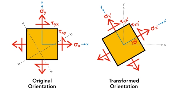 The advantage of the triangular representation is that nosotros can visually identify the transformed stresses on the hypotenuse. However, since we are dealing with ii transformed normal stresses (σx' and σy'), we withal demand two triangles to give complete representation of plane stresses. In the figure below, ΔA is the sectioned area (length of hypotenuse × depth of 3D stress block).
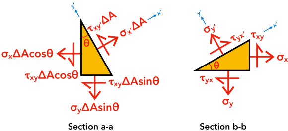
TL;DR
- Stresses change as the airplane on which they act changes orientation. Mohr'south circle "maps" these changes.
- Keeping a consistent sign convention is of import.
- In Pole Method, things are adamant in this society: (σ,τ) → pole → (σ',τ').
- To determine whatsoever transformed airplane country of stress (σ',τ'), we Always starting time at the pole and draw a line parallel to the plane. The signal of intersection on the circle is (σ',τ').
Source: https://structnotes.com/2018/06/23/mohrs-circle/
0 Response to "Draw a Mohrs Circle Diagram for Uniaxial Compression"
แสดงความคิดเห็น